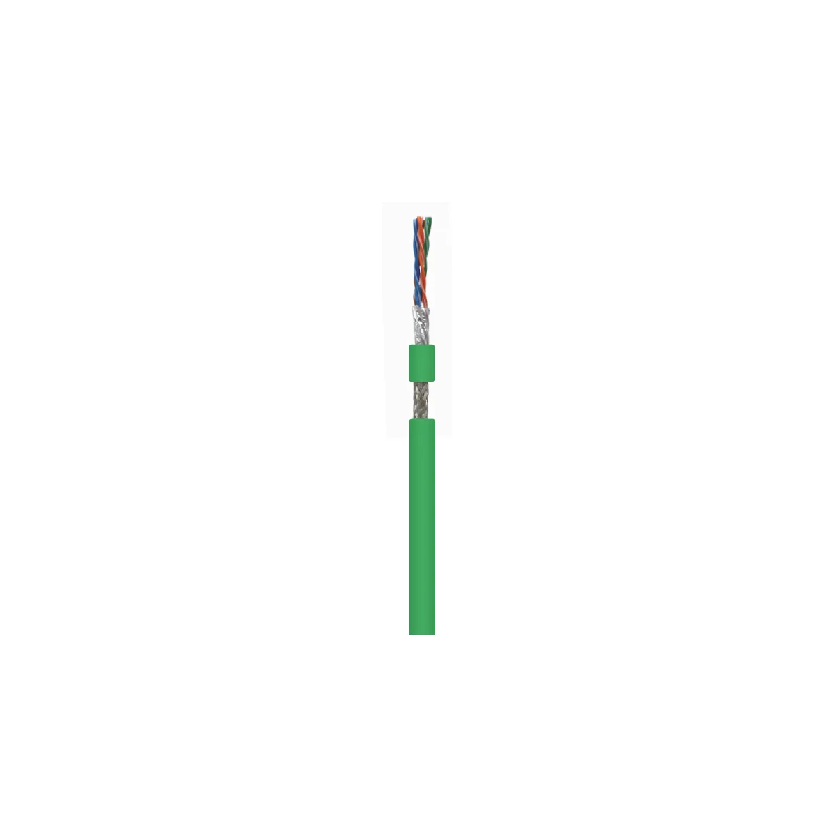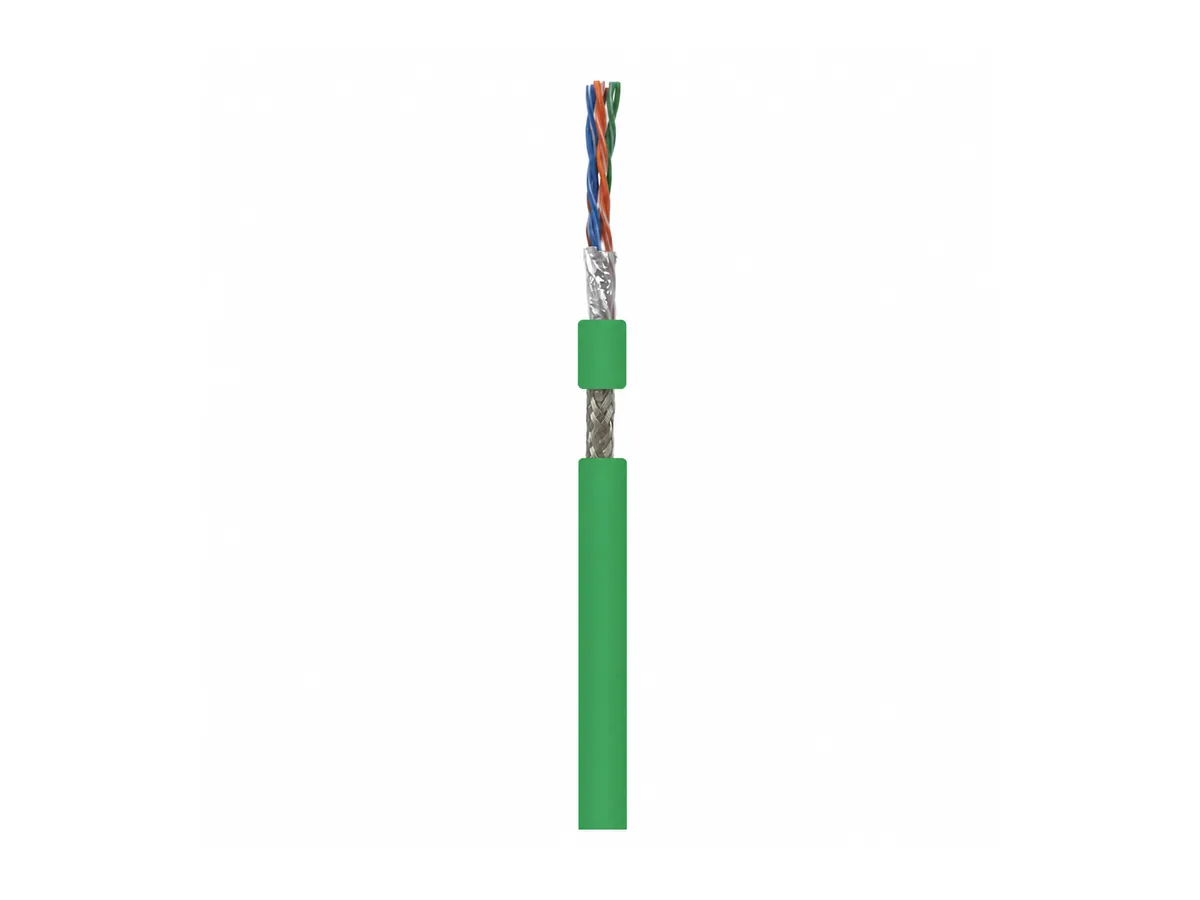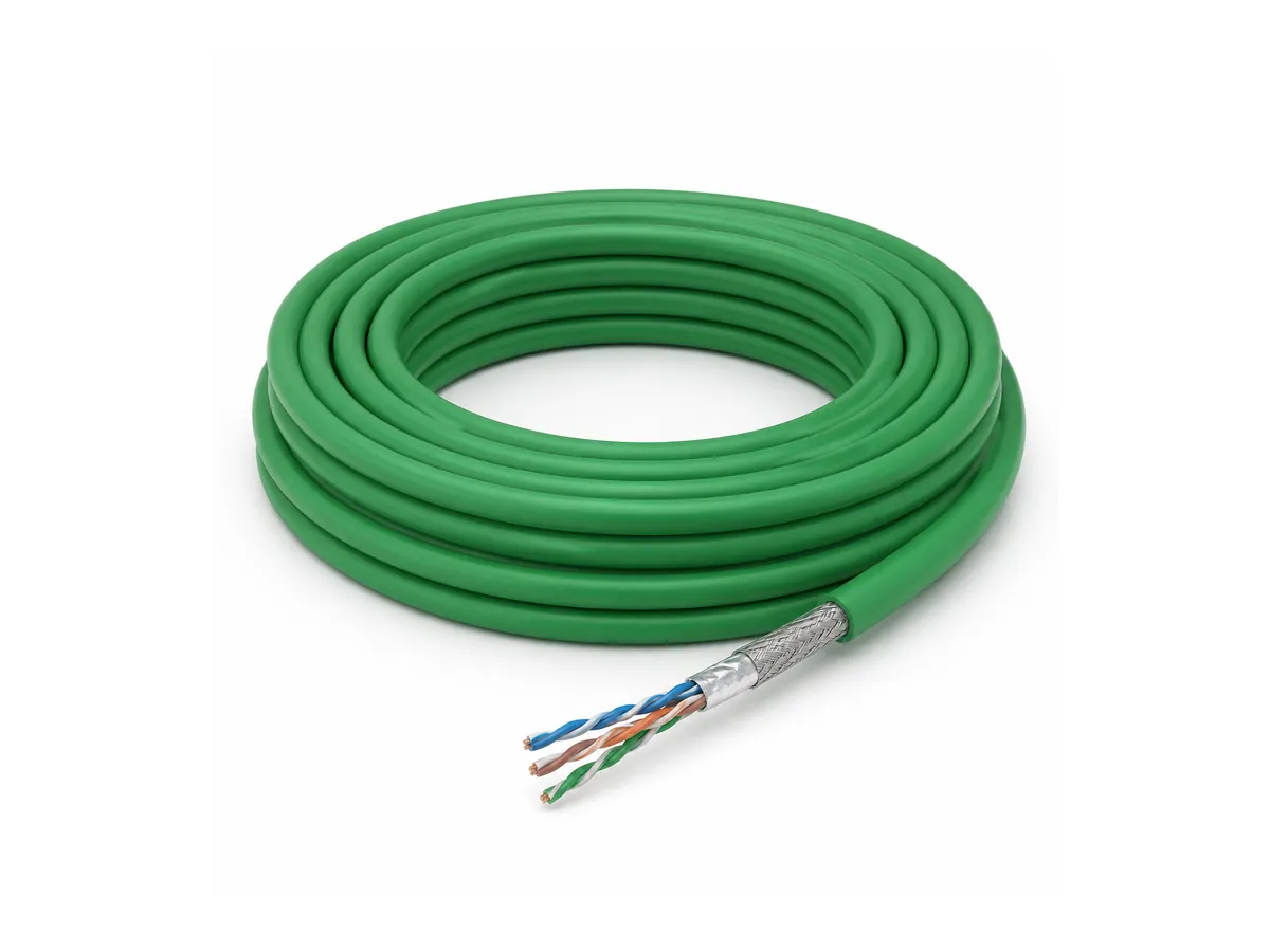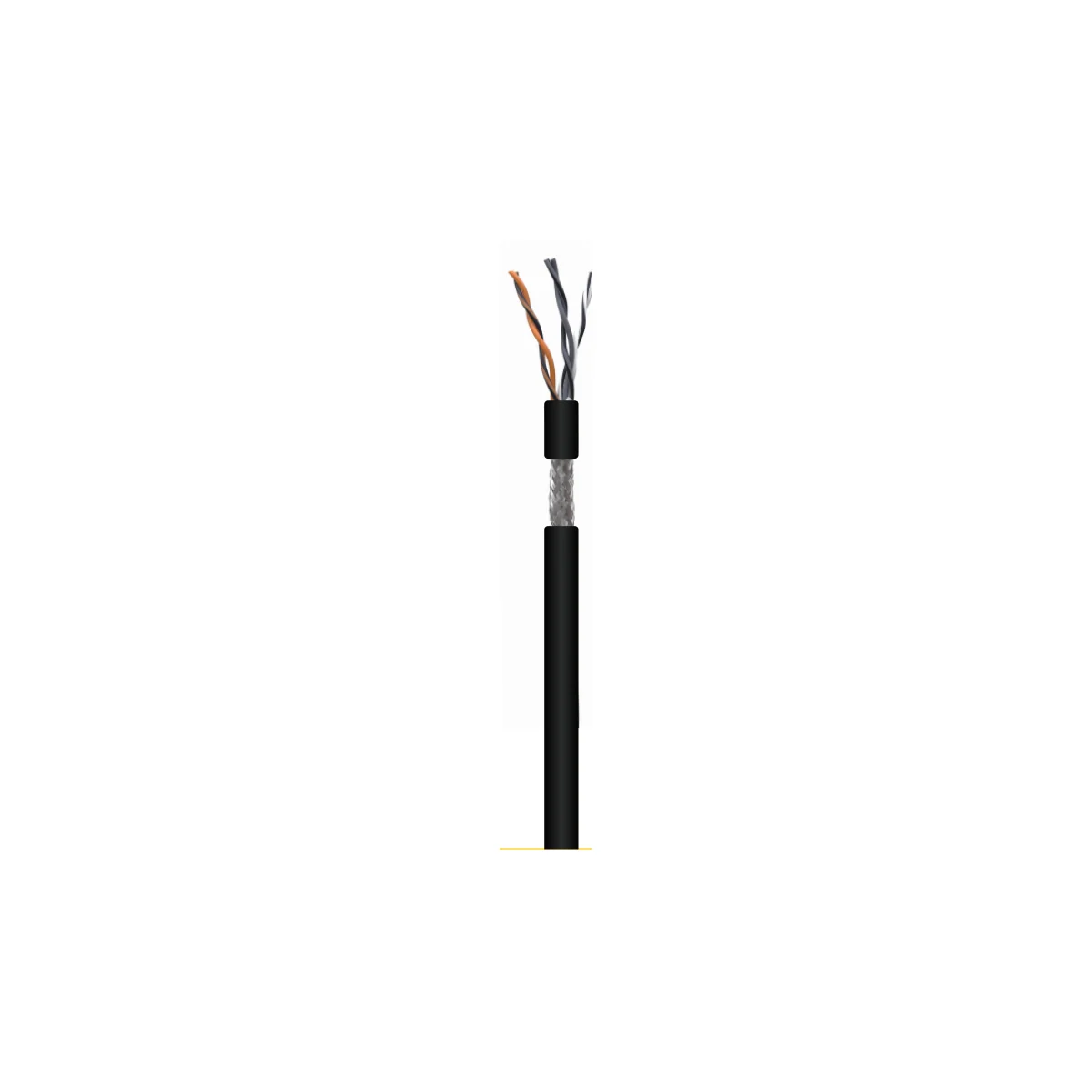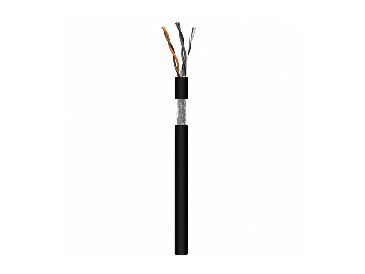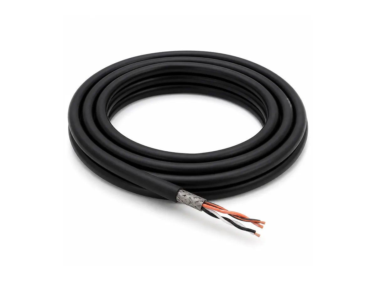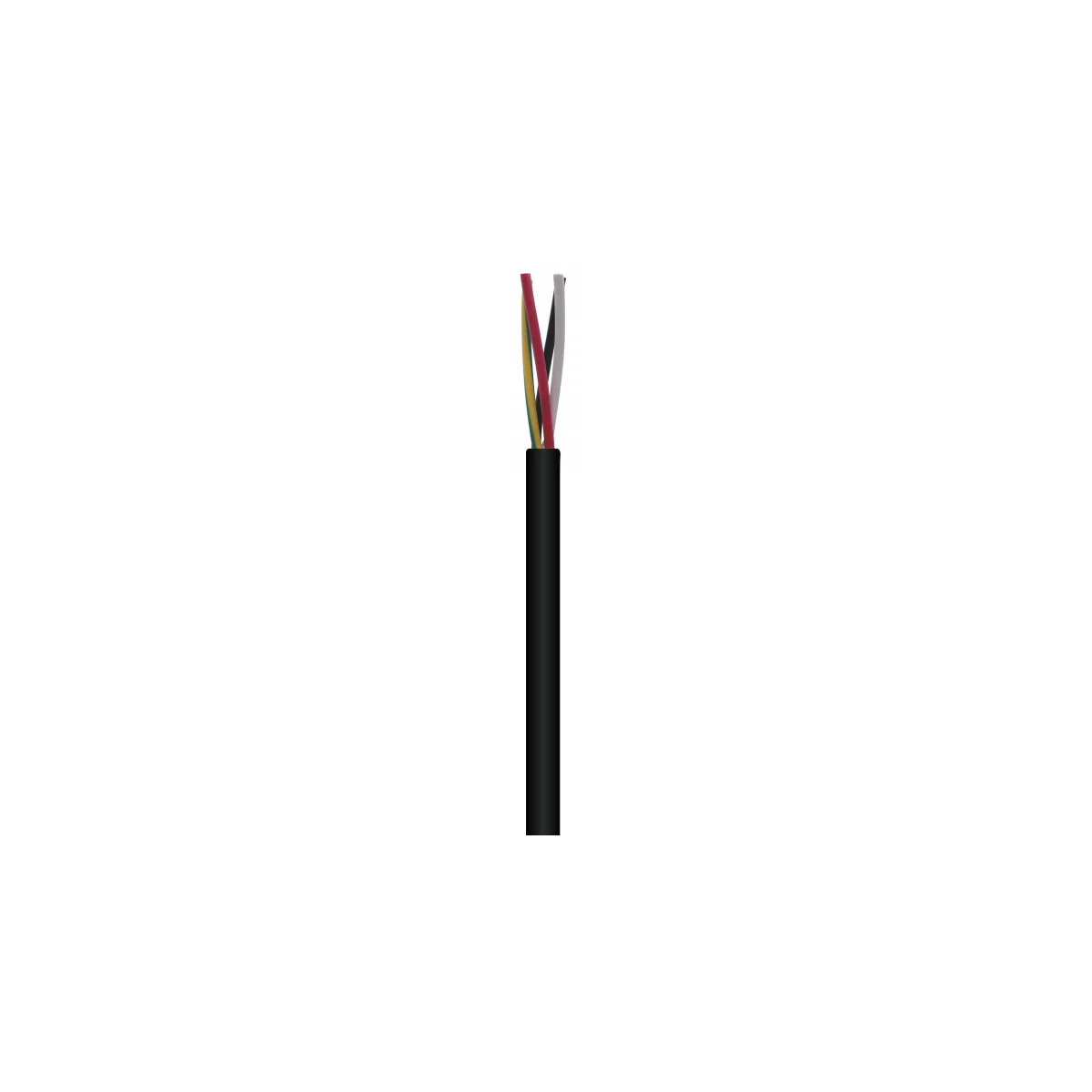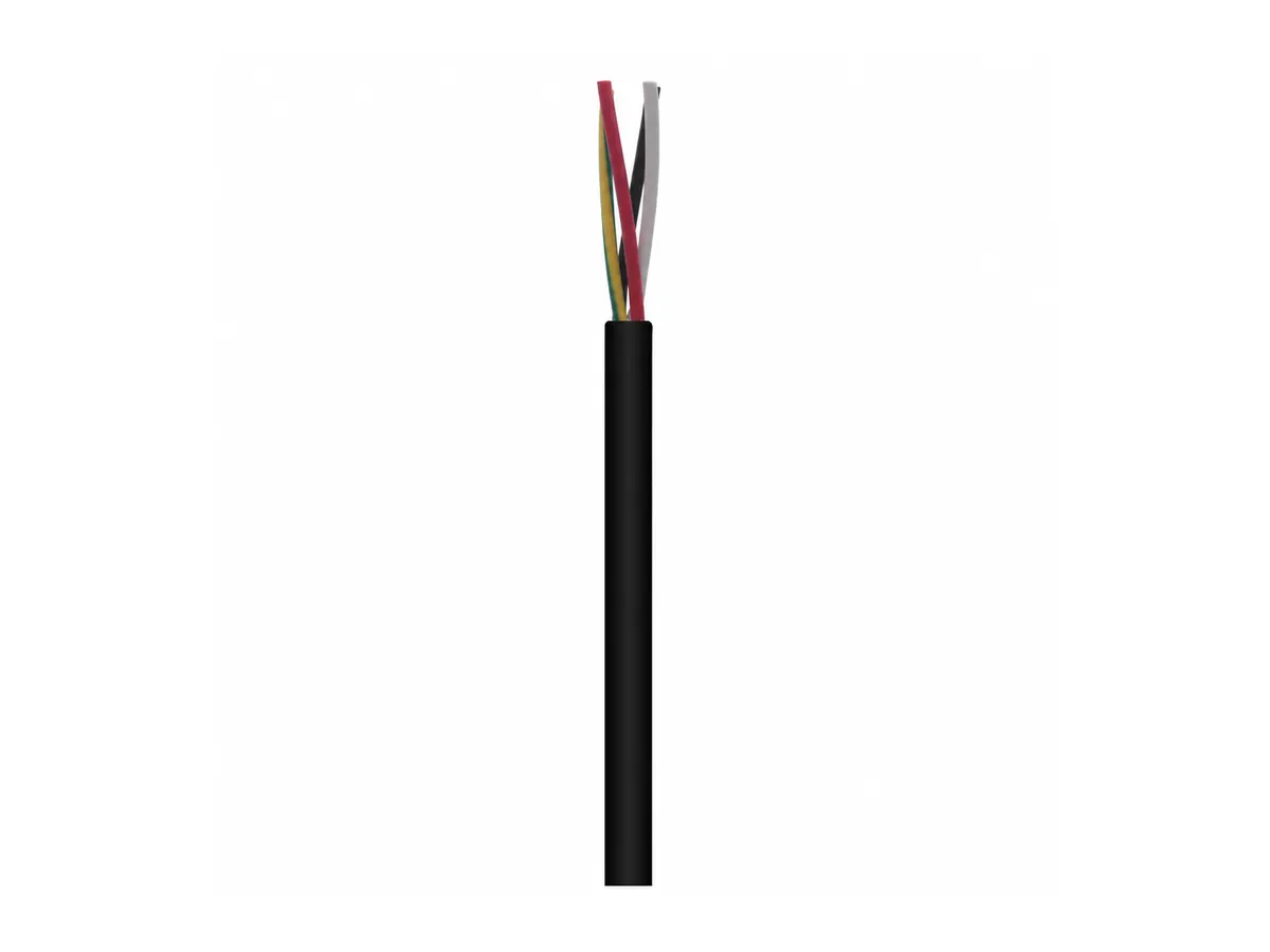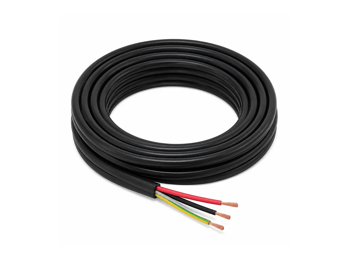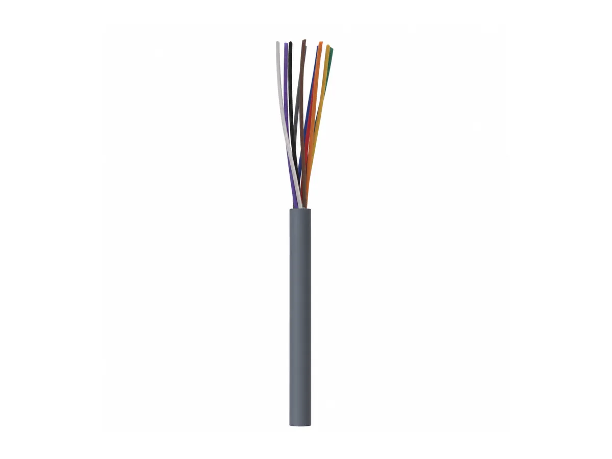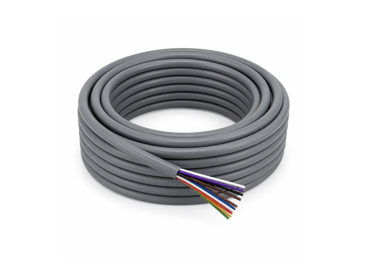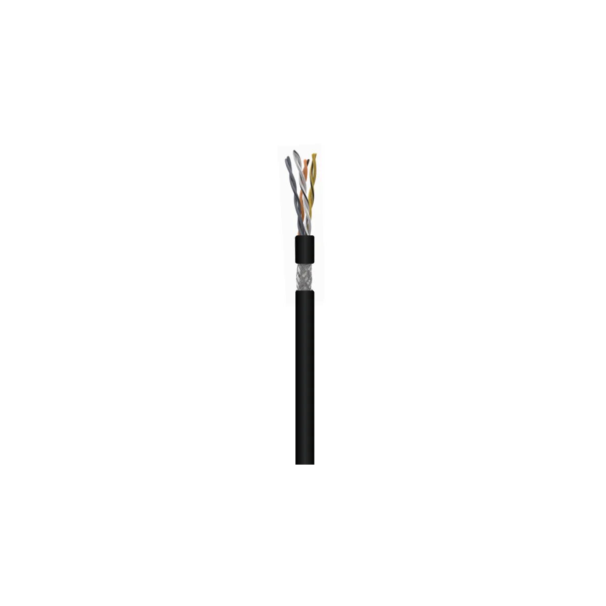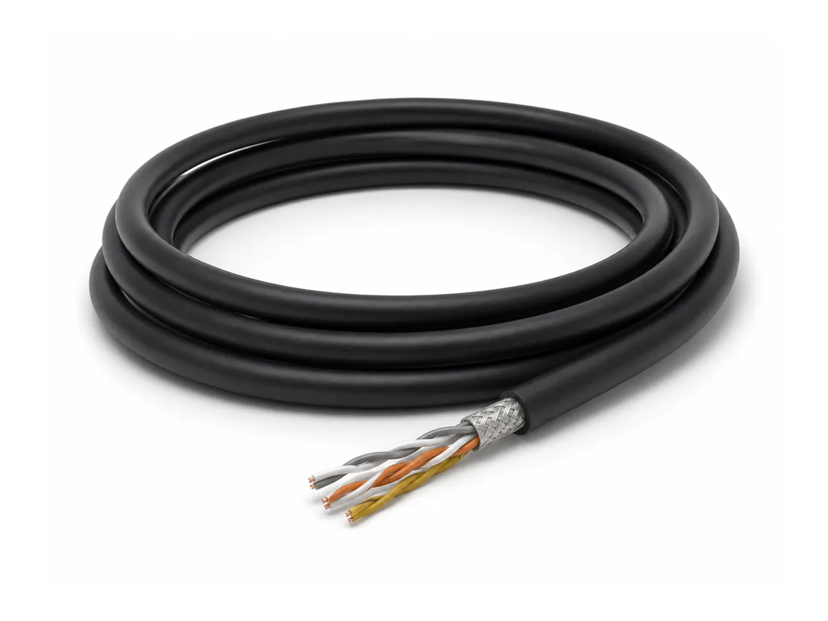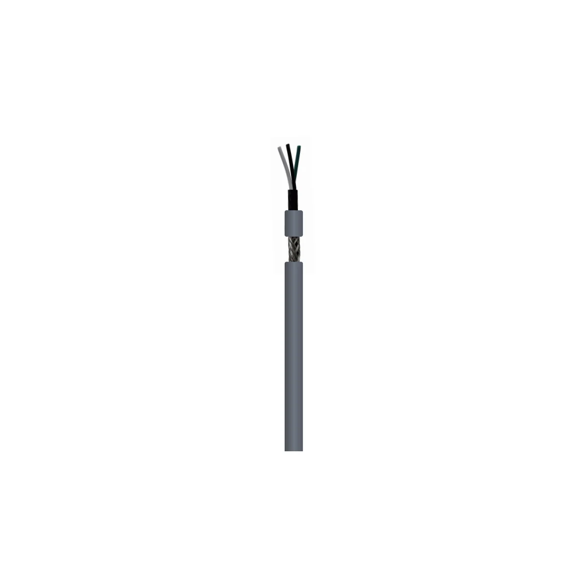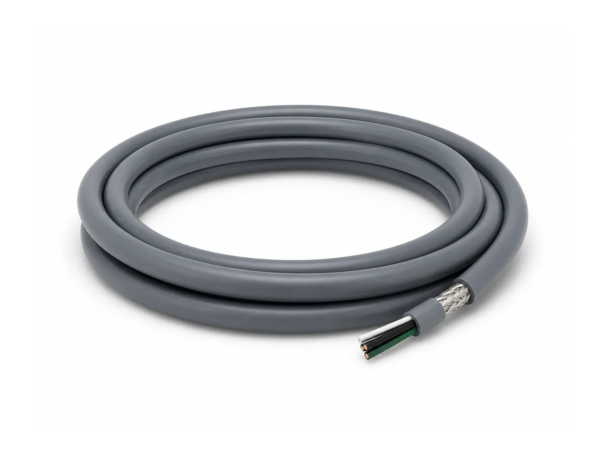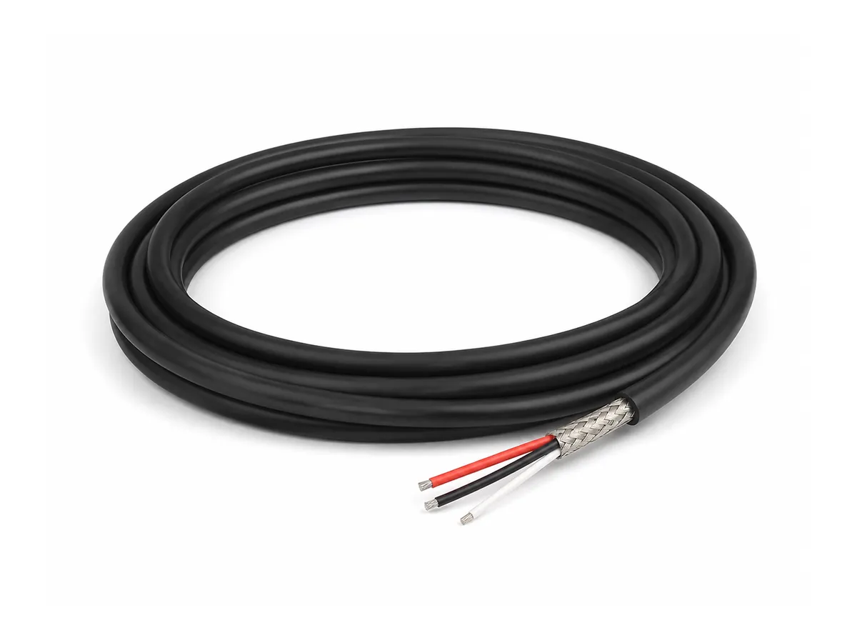
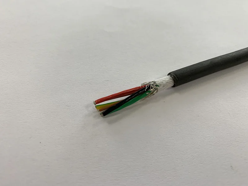
Robot cables carry power, control, encoder feedback, safety signals and industrial data while the machine moves. Unlike ordinary fixed wiring, they may experience millions of bending cycles, rapid acceleration, torsion or combined motion. The correct cable therefore depends on the robot axis and routing—not only on conductor count and voltage.
Start With the Motion Pattern
Linear continuous flex occurs in drag chains where the cable bends repeatedly in one plane. Torsional motion occurs on robot arms where the cable twists around its longitudinal axis. Combined motion may include bending, twisting and changing tension. A cable qualified for one motion should not automatically be assumed suitable for another.
Key Construction Elements
Fine-Stranded Conductors
Flexible conductor designs distribute mechanical strain across many small strands. Strand size, lay length, conductor class and bunching method influence flexibility and fatigue resistance. The conductor must also meet the required electrical resistance and current capacity.
Core Arrangement
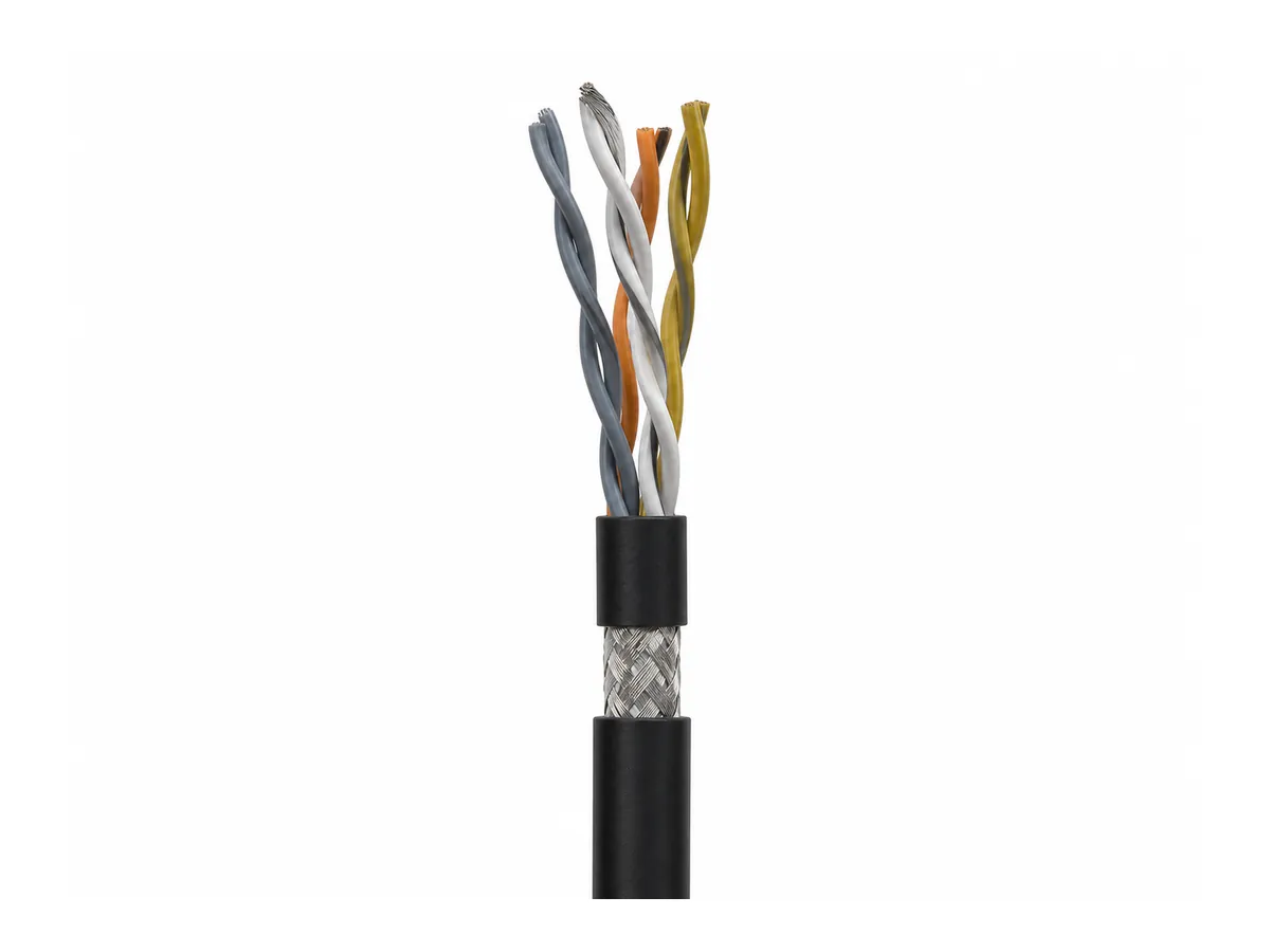
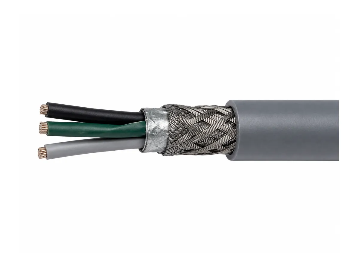
Balanced core geometry, suitable lay lengths, fillers and separators help the cable move without excessive internal stress. Mixed constructions may combine power conductors, twisted signal pairs and feedback circuits, but each element must be arranged for the intended motion.
Shielding
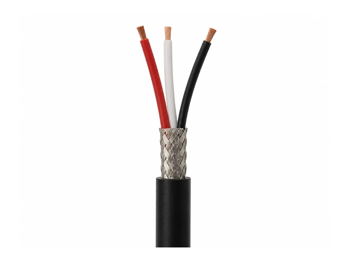
Braided or wrapped shields may be used for electromagnetic compatibility. Shield coverage, drain wires, pair shielding and grounding strategy depend on signal type and equipment design. The shield must maintain electrical continuity while tolerating movement.
Insulation and Jacket
PVC, PUR, TPE and other compounds offer different combinations of flexibility, abrasion behavior, oil resistance and temperature performance. Material claims should be based on the selected compound and test data. A tough jacket alone cannot compensate for unsuitable conductor or core construction.
Power, Control, Encoder and Data Cables
Robot power cables supply motors and actuators. Control cables connect sensors, brakes and I/O devices. Encoder and feedback cables require stable signal transmission and carefully controlled shielding. Industrial Ethernet or fieldbus cables must also preserve the electrical geometry needed for communication under repeated movement.
Selection Data Buyers Should Provide
- Robot type, axis and cable routing
- Linear bend, torsion or combined motion
- Minimum bend radius and available installation space
- Torsion angle and torsion length, where applicable
- Travel distance, speed, acceleration and cycle frequency
- Voltage, current, conductor count, pair configuration and shielding
- Temperature, oil, coolant, abrasion and chemical exposure
- Required connectors, pinout, length, markings and approvals
Installation Practices Matter
Respect the manufacturer’s dynamic bend radius, avoid twisting a linear-flex cable during installation, distribute cables correctly inside the carrier and provide strain relief at fixed ends. Overfilled drag chains, crossed cables and tight clamps can shorten service life even when the cable construction is appropriate.
Qualification and Quality Control
Useful validation includes conductor resistance, insulation and voltage tests, shielding continuity, dimensional inspection and application-specific flex or torsion testing. Cycle-life results are meaningful only when the bend radius, travel, speed, load, temperature and failure criteria are stated.
Conclusion
A robot cable is an engineered moving connection, not simply a soft cable. Defining the motion, electrical function and environment allows the manufacturer to select a construction and qualification plan that matches the real machine duty.
Discuss Your Cable Requirement
Explore our cable product range and best-selling cable solutions. Send us the intended standard, electrical requirements, installation conditions, drawing and order quantity for a technical review and quotation.